Data Center Infrastructure + Operations

Build the power.Unlock the compute.

I-Vintage brings AI infrastructure online — from utility planning and custom transformers to liquid-cooled pods, commissioning, and operational handover.

One platform. Every layer.

The repeatable 1 MW building block.

Standardized infrastructure for AI, HPC, private cloud, and edge deployments. Deploy one module. Then scale the architecture — not the complexity.

1 MWrepeatable deployment unit
1→10+MW campus scalability
480Y/277 Vtypical low-voltage delivery
100+ MVAsubstation transformer range

End-to-end project support

  1. Site & utility planning
  2. Electrical design
  3. Cooling design
  4. Equipment procurement
  5. Construction coordination
  6. Testing & commissioning
  7. Operational readiness

The 1 MW model stack

From grid edge to GPU.

The facility is a system. I-Vintage coordinates each dependency so power, cooling, and compute arrive as one operating architecture.

  1. Utility / Power SourceGrid edge
  2. Transformer & SwitchgearVoltage + protection
  3. UPS & Energy StorageResilience
  4. Power DistributionBusway + PDU
  5. Liquid CoolingHeat transport
  6. GPU RacksAI compute

Power infrastructure

Every volt. Engineered to land.

From utility interconnection to rack-level delivery, I-Vintage supplies the electrical backbone — and the transformer portfolio to match the load.

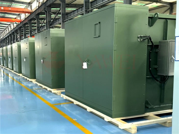
Rows of pad-mounted transformers on a manufacturing floor

Custom-engineered transformer supply

UL-certified manufacturing and ISO-quality systems through qualified global partners.

Transformer Portfolio

Purpose-built for data center harmonic loads.

From 160 kVA K-factor units to 10 MVA pad-mounts, specify windings, ratings, accessories, and application requirements around the facility — not the catalog.

  • Pad-mounted2.5 / 3.75 / 5 MVA reference sizes
  • Typical primary34.5 / 13.8 / 12.47 kV
  • Secondary480Y/277 V
  • Substation class10–100+ MVA
PortfolioRating rangeEfficiencyApplication
K-Factor Rated Transformers160–1,500 kVA98.1–98.65% DOEUL 1561Aluminum or copper windings; mitigates harmonic losses from nonlinear IT loads.
LV Dry-Type General Purpose15 kVA–10 MVA97.89–99.02% DOEISO 9001Reduced harmonic distortion for sensitive electronic environments.
Pad-Mounted Transformers50 kVA–10 MVA98.95–99.33% DOEIndoor / outdoorOil-filled; broad configuration and accessory options.
High-Voltage ComponentsProject-specificSpecified by dutyCritical infrastructureBushings, OLTC-related components, and engineered accessories.

Transformer portfolio capabilities informed by the supplied reference manufacturer. View reference ↗

Liquid cooling

Move heat. Keep density.

Direct-to-chip infrastructure brings cooling closer to compute. I-Vintage connects rack, row, pod, and facility loops as one thermal system.
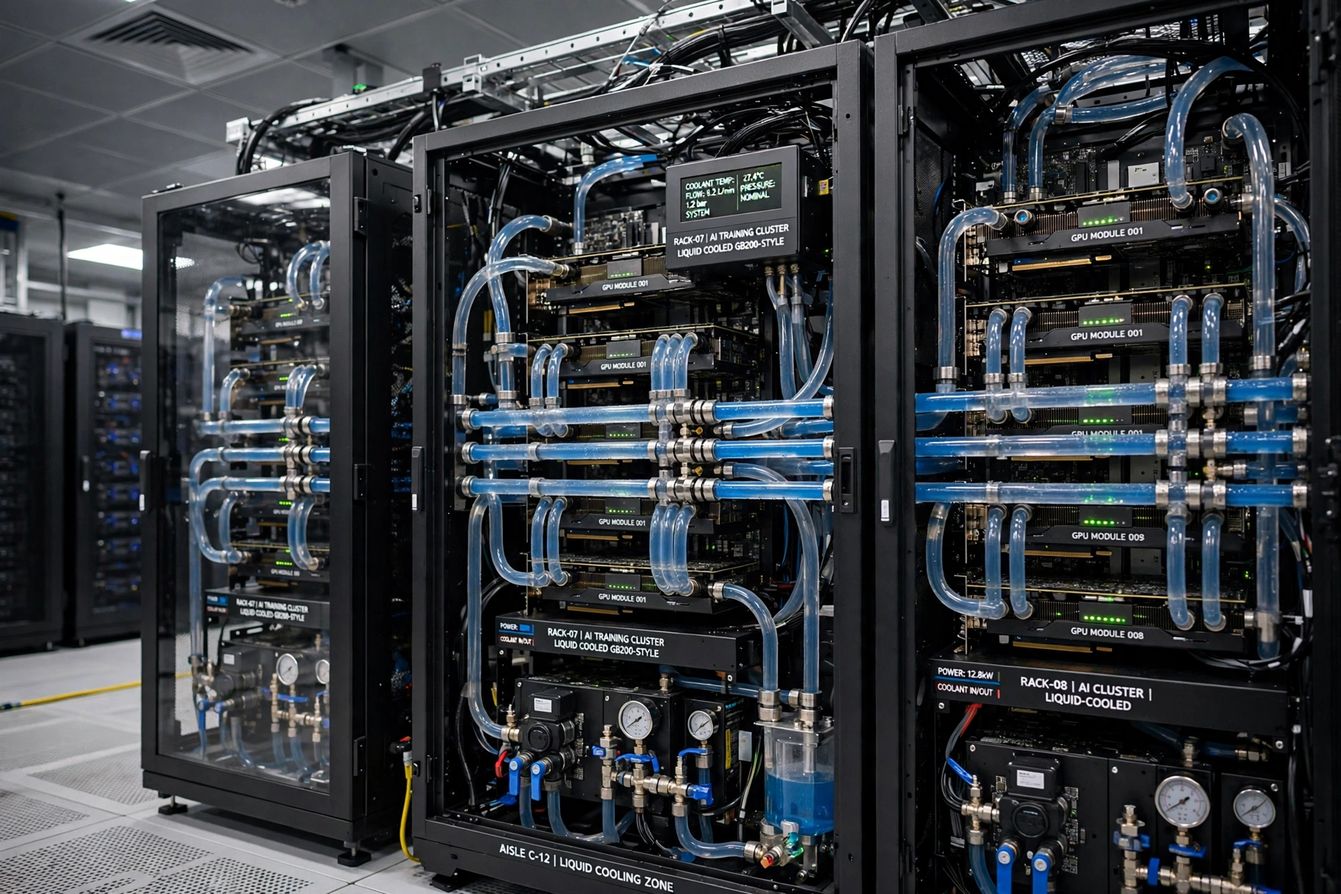
Liquid-cooled GPU racks with visible coolant lines and manifolds

Cooling distribution, rack to facility.

CDUs, manifolds, piping, heat exchange, controls, and facility heat rejection.

CDUs

Control the loop.

Rack- and row-level coolant distribution for direct-to-chip deployments, integrated with facility water and monitoring.

Cooling pods

Deploy as a system.

Pre-engineered modules coordinate racks, distribution, manifolds, pumping, heat exchange, and controls.

High-density racks

Ready for the thermal reality.

Infrastructure designed around sustained AI loads, maintainability, and clear separation between technology and facility loops.

Modular data center pods

Repeat the known. Scale the proven.

A coordinated family of IT, power, and cooling modules creates a repeatable deployment path from 1 MW to multi-megawatt campuses.
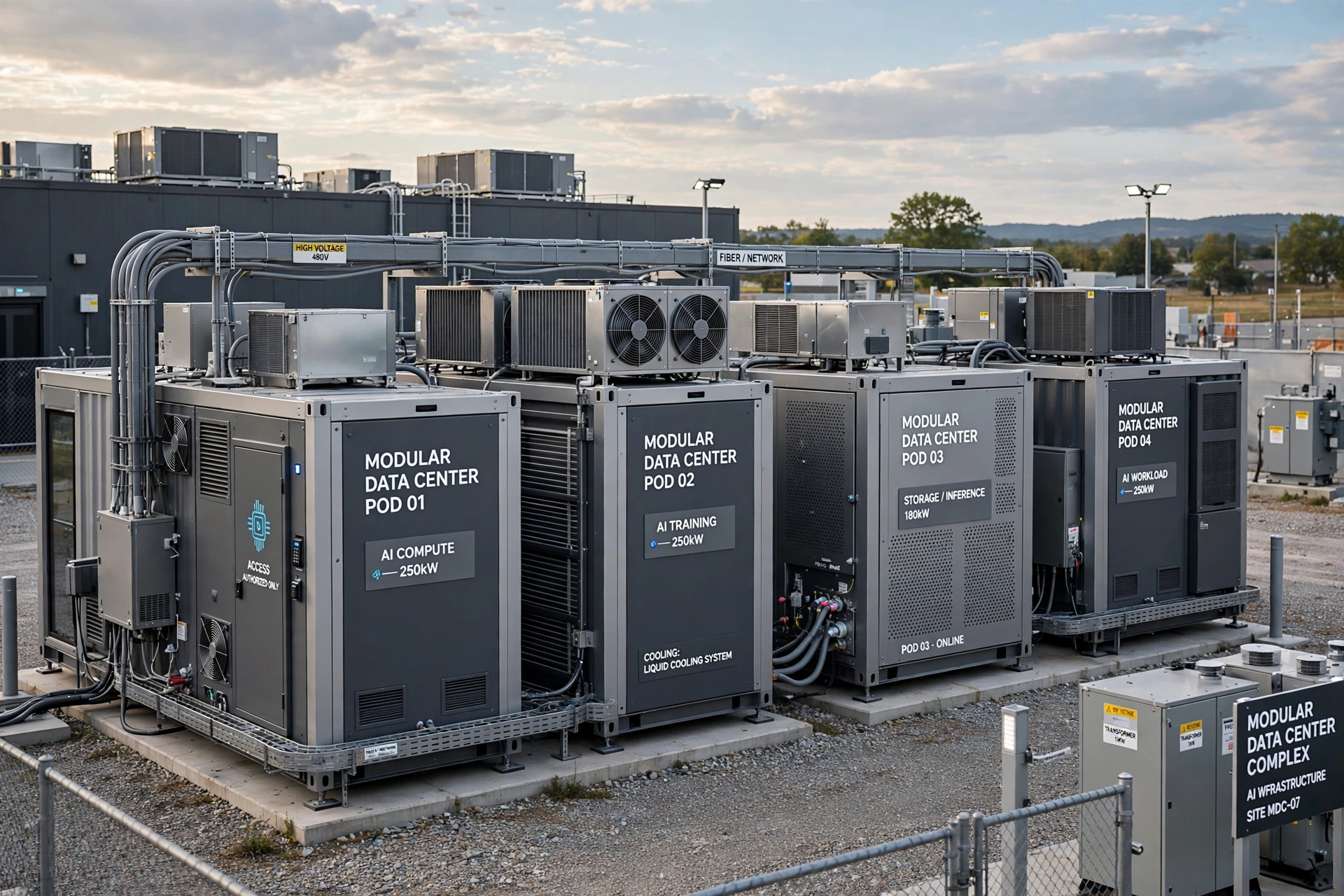
Modular data center pods installed beside a facility

Infrastructure that arrives integrated.

Containerized and skid-based modules built around a shared architecture.

Four modules. One operating model.

IT podsPower podsCooling podsIntegrated modules
  • IThigh-density racks + network
  • Powertransformers, UPS, batteries
  • CoolingCDUs, pumps, exchangers
  • Controlsmonitoring + operating interface

Infrastructure services

Specify. Source. Deliver.

Engineering and manufacturing services that turn electrical requirements into equipment ready for the site.

01 / ENGINEERING

Custom transformer engineering & design

Application-engineered power solutions designed to specification — from voltage and winding selection to enclosure, protection, harmonic duty, and accessories.

02 / MANUFACTURING

Certified manufacturing partnerships

UL-certified, ISO-quality manufacturing through qualified partners across the United States, India, and global markets.

03 / APPLICATION

Built for the load.

Harmonic-mitigating K-factor transformers for nonlinear IT loads, plus dry-type, pad-mounted, substation, and high-voltage component solutions.

04 / DELIVERY

End-to-end project services

Design coordination, sourcing, quality assurance, logistics, construction interface, testing, and commissioning support — one accountable workstream.

I-Vintage Operations & Readiness

Open with the confidence to operate.

AI-assisted engineering and operations services connect design intent, equipment records, procedures, field evidence, and the people who will run the facility.

  1. 01
    Commissioning readiness

    Close gaps across as-builts, manuals, test records, and readiness gates before go-live.

  2. 02
    Procedure development & review

    Develop and review MOPs and SOPs against facility drawings, equipment, and design intent.

  3. 03
    Field execution support

    Guide equipment verification and capture traceable evidence during commissioning.

  4. 04
    Maintenance planning

    Build preventive maintenance schedules from equipment records and manufacturer requirements.

  5. 05
    Operational handover

    Turn a finished build into a facility the client team is ready to run — with connected documentation and clear operating rules.

Equipment supply

Critical equipment. Coordinated as one.

I-Vintage aligns equipment selection, manufacturing, logistics, interfaces, and commissioning across the facility stack.

Transformers

K-factor, dry-type, pad-mounted, substation, and custom-engineered units.

Switchgear

Medium- and low-voltage distribution, protection, metering, and controls.

UPS & batteries

Resilient ride-through and energy storage matched to critical-load strategy.

Power distribution

Busway, PDUs, rack-level delivery, and coordinated branch distribution.

Liquid cooling

CDUs, manifolds, piping, heat exchangers, pumps, and controls.

Backup power

Generator systems and associated distribution for the resilience model.

Modular pods

IT, power, cooling, and integrated deployment modules.

HV components

Bushings, OLTC-related components, and critical transformer accessories.

Quality & logistics

Supplier coordination, documentation, inspections, delivery sequencing, and site interface.

Project Thor

The physical infrastructure behind AI.

A focused I-Vintage initiative to compress uncertainty across power, transformers, high-voltage components, liquid cooling, modular systems, and the supply chain.

  • Power infrastructure
  • Transformer supply
  • Liquid cooling systems
  • Modular data centers
  • High-voltage components
  • Supply-chain development

Insights

Engineering the next power curve.

Practical perspectives on the electrical, thermal, and operating decisions shaping AI infrastructure.

POWER ARCHITECTURE · 8 MIN READ

The 800V inflection point: why data center power distribution is moving to 800 VDC

Higher rack density is forcing a rethink of current, copper, conversion stages, and the path from today’s 415/480V AC facilities.

THERMAL SYSTEMS · 7 MIN READ

Liquid cooling for the AI era: direct-to-chip and facility heat rejection

Cold plates are only the beginning. The real design spans rack loops, CDUs, water chemistry, controls, and outdoor heat rejection.

ELECTRICAL DESIGN · 8 MIN READ

Sizing power for 1 MW AI facilities: transformers, switchgear, and harmonic mitigation

A 1 MW IT target is not a 1 MW service. Translate compute demand into a realistic electrical one-line with capacity and power quality intact.

MODULAR DELIVERY · 6 MIN READ

Modular data center pods: from 1 MW to 10 MW+ without rebuilding

Scaling works when interfaces repeat — not merely when containers do. Standardize the architecture, then preserve room for technology change.

Literature

Technical briefs for decisive teams.

Compact references for owners, developers, engineers, operators, and procurement leaders.

Technical Brief · PDF · 12 pages

800V-Ready Facility Design Guide

Decision gates, distribution boundaries, safety considerations, and migration paths for projects starting at 415/480V AC.

Request brief ↗
Design Guide · PDF · 16 pages

The 1 MW AI Infrastructure Stack

A system view of utility, transformation, resilience, distribution, liquid cooling, and GPU delivery.

Request guide ↗
Specification Note · PDF · 10 pages

Transformer Selection for Nonlinear IT Loads

K-factor, winding, efficiency, voltage, accessories, and harmonic-duty considerations for data centers.

Request note ↗

Why I-Vintage

Infrastructure intelligence, all the way through operations.

Technology fluencyRequirements begin with the workload, not a generic facility template.
Planning disciplineUtility, electrical, thermal, civil, and operational dependencies stay connected.
Procurement reachQualified manufacturing relationships across US, India, and global markets.
Project coordinationInterfaces are managed from source through delivery and commissioning.
Operational readinessDocumentation, procedures, evidence, and maintenance planning arrive with the facility.
Scalable architectureRepeatable 1 MW modules create a path to 2, 5, 10 MW and beyond.

Start with the constraint

Tell us what must come online.

Bring the site, utility condition, rack roadmap, delivery target, or supply-chain bottleneck. I-Vintage will structure the path from infrastructure to operation.

Talk to an Expert +1 702-879-9954 Share your site, power, cooling, equipment, and readiness requirements and our team will get back to you.
POWER ARCHITECTURE · 8 MIN READ

The 800V inflection point

AI factories are changing the electrical problem inside the data center. The issue is not simply that racks consume more power. It is that moving hundreds of kilowatts to a single rack at conventional distribution voltages creates current levels that multiply conductor size, busway mass, connection count, and I²R losses. An 800 VDC distribution layer is emerging because it attacks those constraints at the architecture level.

Why voltage matters

For a given power level, raising voltage reduces current. That relationship is the core economic lever. Lower current can mean less copper, smaller conductors, fewer parallel runs, reduced busway cross-section, and lower resistive losses. It may also simplify the physical challenge of delivering power to dense GPU rows where cable pathways and connection points have become limiting resources. The value is therefore not one efficiency percentage; it is a coordinated reduction in electrical material, thermal loss, and installation complexity.

But 800 VDC is not a drop-in substitute for 415/480V AC. Today’s facilities are built around mature switchgear, protection practices, UPS topologies, maintenance procedures, and code frameworks. DC interruption behaves differently from AC because the current has no natural zero crossing. Protection coordination, connector design, isolation, grounding strategy, arc-energy analysis, fault detection, and safe service methods must evolve together.

The transition architecture

Most projects will not jump from utility service directly to an all-DC facility. A practical transition retains medium-voltage utility intake and familiar facility distribution while placing conversion closer to the IT domain. The exact boundary may sit at a power room, row, pod, or rack. Each choice changes conversion count, fault domains, maintainability, redundancy, and the amount of DC distribution exposed to the white space.

Design teams should evaluate the full chain: utility transformer, medium- and low-voltage switchgear, UPS or energy storage, AC/DC conversion, busway, rack power shelves, and board-level conversion. Removing one conversion stage can improve end-to-end efficiency, but only if the replacement architecture preserves ride-through, selective coordination, and serviceability. Nameplate efficiency at a single load point is not enough; model the expected operating envelope and redundancy state.

Build 800V-ready before buying 800V gear

A sound near-term strategy is readiness without premature commitment. Reserve electrical rooms and pathways, establish modular connection points, protect clearance and ventilation envelopes, separate technology loops from long-life facility infrastructure, and define controls capable of monitoring both AC and future DC segments. Specify short-circuit, grounding, and safety studies that can be updated when a named rack platform is selected.

The right trigger is not excitement around a voltage. It is a contracted workload, a defined rack platform, a verified equipment ecosystem, and an economic model that includes copper, conversion losses, installation labor, protection, spares, training, and schedule risk. Until those inputs are real, 415/480V AC remains the mature baseline. The inflection point arrives when 800 VDC reduces total system complexity—not when it merely moves complexity to a less familiar layer.

THERMAL SYSTEMS · 7 MIN READ

Liquid cooling for the AI era

Direct-to-chip cooling is often described as a rack technology. In practice, it is a facility-wide heat-transport system. A cold plate may remove heat from a GPU, but the design succeeds only when every interface—from server quick disconnect to campus heat rejection—operates within a controlled temperature, pressure, flow, chemistry, and failure envelope.

Two loops, one thermal objective

Most architectures separate a technology cooling system from facility water through a coolant distribution unit. The technology loop serves cold plates and rack manifolds with tightly controlled fluid quality. The facility loop carries that heat to chillers, dry coolers, cooling towers, or another heat-rejection system. The CDU is therefore more than a pump package. It establishes hydraulic separation, heat exchange, filtration, monitoring, control, and often redundancy between loops with different operating requirements.

Rack-level CDUs can isolate smaller fault domains and support incremental deployment. Row-level units may simplify service access and aggregate capacity. Facility-scale units can reduce equipment count but concentrate consequences. The correct tier depends on rack density, white-space geometry, water availability, service model, deployment cadence, and the client’s tolerance for shared failure modes.

Design from the heat rejection backward

Supply temperature defines opportunity. Warmer coolant can expand the hours available for economization and reduce or eliminate mechanical refrigeration in suitable climates. Yet higher supply temperatures must remain compatible with silicon limits, server controls, approach temperatures, and transient conditions. A credible design models peak ambient conditions, part-load behavior, pump energy, fouling, water treatment, and the loss of a critical component—not only a nominal design day.

Flow and pressure also demand system thinking. Parallel rack branches need balancing. Pumps need stable control across changing server populations. Manifolds and quick disconnects must be selected for pressure drop, materials compatibility, leak behavior, serviceability, and monitoring. Water chemistry requirements must be agreed across server, CDU, piping, and facility vendors; otherwise warranties and operating practices can conflict at handover.

Commission the interfaces

Liquid cooling commissioning should prove more than flow. Teams should verify flushing and cleanliness, pressure integrity, leak detection, pump sequencing, control-valve response, alarm routing, failover, thermal performance, and safe maintenance isolation. Simulated load or controlled heat injection can reveal control instability before GPU clusters carry production work.

The operating model matters as much as the mechanical design. Procedures must cover filling, draining, air removal, sampling, filter changes, connector service, leak response, and restoration after an event. Spare strategy should include pumps, seals, sensors, hoses, and quick disconnects selected by actual failure consequence. When those requirements are linked to drawings, equipment records, and field evidence, direct-to-chip cooling becomes an operational capability rather than an equipment purchase.

ELECTRICAL DESIGN · 8 MIN READ

Sizing power for 1 MW AI facilities

A 1 MW IT target is the start of an electrical design, not the service size. The facility must also power cooling, pumps, fans, controls, lighting, security, and conversion losses. It must tolerate the selected redundancy condition, expected growth, ambient derating, maintenance states, and the non-linear behavior of modern power electronics. The correct service emerges from a load model with explicit assumptions.

Separate IT nameplate from operating demand

GPU rack nameplate ratings can exceed expected average load, yet optimistic diversity can strand capacity when workloads become synchronized. Build the model at rack and distribution-block level. Define initial and ultimate rack counts, normal operating load, plausible sustained peak, diversity, and future technology envelope. Then add mechanical and electrical overhead based on the actual cooling architecture rather than a generic PUE placeholder.

Redundancy changes equipment loading. In an N+1 system, remaining modules may carry more load after a failure. In a 2N system, each side must support the critical path, but normal loading and efficiency may differ. Transformer and switchgear selection should be checked in normal, failure, maintenance, and expansion states. Temperature rise, enclosure, altitude, ambient temperature, and harmonic duty can all alter usable capacity.

Transformers and harmonic loads

IT power supplies and variable-frequency drives are nonlinear loads. They draw current in waveforms that contain harmonics, which can increase winding and eddy-current losses, neutral current, heating, and voltage distortion. K-factor-rated transformers are one tool for accommodating defined harmonic content. They do not remove harmonics; they are constructed to tolerate the additional heating associated with them. The study must still evaluate total harmonic distortion, upstream impedance, capacitor interaction, generator compatibility, and the need for mitigation.

For a standardized 1 MW block, pad-mounted transformers in the 2.5, 3.75, or 5 MVA class may be considered depending on facility overhead, redundancy, voltage architecture, and growth strategy. Typical utility primary voltages may include 34.5, 13.8, or 12.47 kV with 480Y/277 V secondary distribution, but the local utility standard and fault contribution govern the actual design. Campus substations can require transformer capacities from 10 MVA into the 100+ MVA range.

Coordinate the protection system

Available fault current drives equipment ratings and protection choices. A selective coordination study should examine utility source characteristics, transformer impedance, generator contribution, UPS behavior, and downstream devices. Arc-flash energy, clearing time, maintenance settings, and zone-selective interlocking must be considered alongside uptime. The goal is not merely to interrupt a fault; it is to isolate the smallest practical fault domain without exposing operators to unacceptable risk.

Finally, preserve expansion logic. A one-line that works at 1 MW can become awkward at 5 MW if tie points, bus ratings, relay philosophy, space, and utility phasing were never planned. Define the ultimate campus topology early, then commission each block as a complete protection, power-quality, and operating system. That is how 1 MW becomes a repeatable unit rather than a one-off project.

MODULAR DELIVERY · 6 MIN READ

Modular data center pods

Modularity is not the act of putting equipment in a container. It is the discipline of defining stable interfaces so a tested building block can be repeated without re-engineering every dependency. For AI infrastructure, the most useful unit is often a coordinated 1 MW stack spanning power, cooling, controls, and IT delivery.

Standardize interfaces, not assumptions

A repeatable pod should define electrical input, output, fault duty, grounding, controls, network, cooling temperatures, flow, pressure, water chemistry, fire strategy, maintenance clearances, lifting points, and commissioning boundaries. Those interfaces must be explicit enough for parallel work across suppliers while remaining adaptable to site conditions and changing rack technology.

The pod family typically includes IT modules, power modules, and cooling modules. Power pods may combine transformers, switchgear, UPS, batteries, and distribution. Cooling pods may integrate CDUs, pumps, heat exchangers, filtration, manifolds, and controls. IT pods provide racks, containment where relevant, distribution, network pathways, monitoring, and connection points. An integrated module can bring these systems together, but the operating boundaries still need to remain visible.

Design the campus before the first block

Scaling from 1 MW to 10 MW+ requires an ultimate-state plan for utility capacity, medium-voltage distribution, protection zones, generators, fuel, heat rejection, water, network, access, fire separation, and control hierarchy. The first block should occupy its place in that plan without forcing later shutdowns or relocations. Stub-outs, tie points, reserved bays, common headers, and staged control logic are inexpensive when designed early and disruptive when retrofitted.

Modularity can also compress schedule by allowing factory assembly and site work to proceed in parallel. That advantage is real only when submittals, interfaces, inspections, and test plans are controlled. Factory acceptance testing should prove functional sequences and record configuration before shipment. Site acceptance then verifies installation, interfaces, protection, controls, and performance under the actual facility conditions.

Keep technology replaceable

Compute evolves faster than utility infrastructure. A strong modular architecture separates long-life assets from fast-changing technology. Medium-voltage equipment, site distribution, and major heat-rejection systems may serve several generations of racks. Rack power shelves, CDUs, manifolds, and controls may change more quickly. Designing clean boundaries between these layers protects the capital base while allowing density and voltage to evolve.

The operating model must repeat too. Equipment naming, alarms, procedures, maintenance intervals, spare parts, training, and turnover documentation should follow a common structure across blocks. When the second and fifth modules arrive, operators should recognize the logic even if a component vendor changes. That is the real promise of modularity: each expansion increases capacity without multiplying ambiguity.